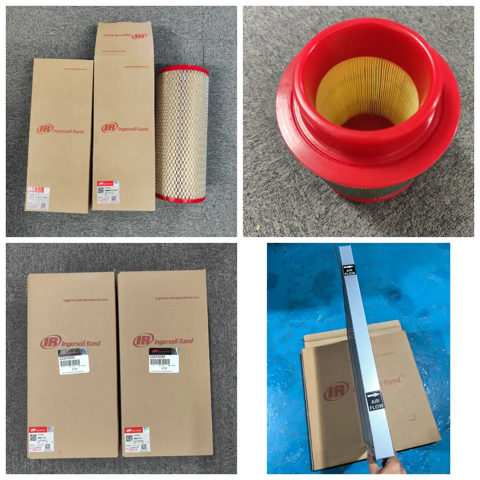
Product
Ingersoll Rand 47701891001 Air Filter Element | Replaces 39903281
Ingersoll Rand 47701891001 air filter element (previous PN 39903281) for 90–160 kW VPeX screw compressors including M350-3S and 125S/150S/175S/200S. 5–10 μm filtration, ≥98% efficiency, approx. 380 mm OD × 178 mm height, 2000 h or 3-month service interval.
- Export packaging & documentation support
- OEM / ODM customization available
- Sample and bulk order workflow
Product Overview
47701891001 is the intake air filter element for Ingersoll Rand oil-lubricated screw compressors. The previous OEM part number 39903281 refers to the same element — older drawings and spare-parts lists usually carry the legacy number.
The element sits inside the external intake filter assembly, upstream of the airend inlet, and forms the first filtration stage on the intake path. Ambient air carries dust, grit, fibres and lint; the media traps these before they reach the screw rotors. Once the element fails, unfiltered air enters the airend and accelerates wear on rotors, bearings and lubricant in sequence.
This element covers the Ingersoll Rand 90–160 kW range, typically M350-3S, 125S/150S/175S/200S, and the ML/MM/MH 90–160, MM90–110, M90/M110 platforms. The power band belongs to the VPeX platform. Same-power NG R-Series and larger M250 units use different air filter part numbers and are not interchangeable (see cross-platform table below).
Core Specifications
| Item | Value |
|---|---|
| Part Number | 47701891001 |
| Previous OEM PN | 39903281 |
| Description | Air Filter Element |
| Brand | Ingersoll Rand |
| Applicable Power Range | 90–160 kW |
| Filtration Rating | 5–10 μm |
| Filtration Efficiency | ≥98% (for particles ≥5 μm) |
| Dimensions | Approx. 380 mm OD × 178 mm overall height |
| Recommended Change Interval | 2000 hours or 3 months |
Basic Parameters
| Parameter | Detail |
|---|---|
| Part Number | 47701891001 |
| Previous OEM PN | 39903281 |
| Brand | Ingersoll Rand |
| Product Name | Air Filter Element |
| Category | Intake filtration (air filter) |
| Applicable Platform | Ingersoll Rand 90–160 kW screw compressors (VPeX platform) |
| Typical Models | M350-3S, 125S/150S/175S/200S, ML/MM/MH 90–160, MM90–110, M90/M110 |
| Installation Position | Inside external intake filter assembly, upstream of airend inlet |
| Quantity per Unit | 2 pcs for 125S–200S series; 1 pc for MM90–110 |
| Change Interval | 2000 hours or 3 months |
How to Confirm Fitment
Several intake configurations exist within the same power band, and part numbers that look similar are not interchangeable. Before ordering, check three points: (1) the part number stamped on the old element end cap or cage matches the ordered number (if the old part reads 39903281, it is the same element); (2) the unit nameplate model and power fall within the 90–160 kW band; (3) the old element's installation position — on two-stage intake systems the main and safety elements differ in position and part number.
Note that 47701890001 shares the same product name but corresponds to a different intake configuration. Verify each by part number; do not substitute based on similar naming.
Technical Specifications
1. Filtration Performance
| Parameter | Value / Note |
|---|---|
| Filtration Rating | 5–10 μm |
| Filtration Efficiency | ≥98% (for particles ≥5 μm) |
| Filter Class | Characterised per ISO 5011 by efficiency, restriction and dust holding capacity; HVAC classifications (G4 / F7 etc.) do not apply |
| Dust Holding Capacity | Directly related to site dust concentration; no universal nominal value — use intake differential pressure gauge reading as the criterion |
Rating and efficiency should be read as a pair. A high-rating element with low dust holding capacity builds restriction quickly and needs frequent replacement, raising total cost of ownership. This design maintains sufficient dust space at 5–10 μm to suit continuously running 90–160 kW units.
2. Flow and Restriction
| Parameter | Value / Note |
|---|---|
| Rated Air Flow | Must not be below unit rated intake; 90–160 kW units typically draw around 15–27 m³/min, based on displacement with intake temperature and altitude correction |
| Initial Pressure Drop | Approx. 0.3–0.5 kPa (clean, new element) |
| Operating Differential Range | Rises with dust loading; typical operating range approx. 0.5–1.5 kPa |
| Alarm / Final Restriction | Typical change threshold approx. 1.5–2.5 kPa; intake vacuum / differential gauge reading is the final criterion |
| Restriction vs. Energy | Each 1 kPa increase in intake restriction raises compression ratio by approx. 1%, increasing unit energy consumption by approx. 1.0% |
Restriction–energy relationship (theoretical, at 0.85 MPa discharge gauge pressure):
| Intake Restriction | Compression Ratio | Energy Increase |
|---|---|---|
| 0 kPa (new) | 9.39 | Baseline |
| 0.5 kPa | 9.44 | +0.5% |
| 1.0 kPa | 9.49 | +1.0% |
| 1.5 kPa | 9.53 | +1.5% |
| 2.0 kPa | 9.58 | +2.0% |
| 2.5 kPa | 9.63 | +2.5% |
From installation to the change threshold, intake restriction rises by more than 2 kPa, adding roughly 2% to energy consumption. Units such as the 125S–200S and M350-3S usually run continuously, and that energy difference typically exceeds the element price — running on a calendar rather than on restriction is not economical.
3. Dimensions and Installation
| Parameter | Value / Note |
|---|---|
| Dimensions | Approx. 380 mm OD × 178 mm overall height (verify against the old part before ordering) |
| Effective Filter Area | Depends on pleat count and depth; confirm from the old element's measured dimensions |
| Pleat Count / Pitch | Varies by production batch and media configuration; count from the old part |
| Mounting Interface | Cylindrical push-in; secured by end cap compression once seated in the intake filter assembly |
| Sealing | Face or radial seal; seal body either integrally moulded with the end cap or fitted separately |
Recommended measurements before ordering a replacement:
| Measurement | Note |
|---|---|
| Outer Diameter | Outer edge of the filter media |
| Inner Diameter | Centre bore diameter |
| Overall Height | Including end caps |
| Seal Position and Type | Face / radial, plus seal cross-section profile |
| Mounting Interface | Clamp, bolt holes or quick-fit design and dimensions |
Outer diameter, overall height and seal type determine whether the element seats correctly and whether bypass occurs. Dimensions on this page are for initial comparison only; the old part measurement is final.
4. Materials of Construction
| Component | Material | Note |
|---|---|---|
| Filter Media | Wood-pulp cellulose fibre paper, pleated | Depth filtration; fibre layers capture particles progressively |
| Media Grammage | Approx. 130 g/m² | Determines burst strength and dust holding space |
| Inner / Outer Cage | Galvanised steel perforated cage | Dual-side support prevents media collapse under negative pressure |
| End Caps | Metal or polyurethane end caps | Bonded to media; also carries the seal |
| Seal | Polyurethane or nitrile rubber seal body | Prevents bypass between element and assembly |
| Bonding | Polyurethane adhesive | Fixes media to end caps and cage; seals edges |
5. Operating Conditions
| Parameter | Value / Note |
|---|---|
| Operating Temperature | -10 °C to +80 °C |
| Relative Humidity | ≤90% RH (non-condensing) |
| Burst / Collapse Resistance | Standard design withstands ≥5 kPa across the media without deformation |
| Special Function | Intake filtration for high-power units; a pre-filter layer can be added in heavy dust to extend main element life |
In high-humidity, high-dust or oil-mist environments (textile, foundry, food, cement), media strength drops once damp and oil mist causes surface mud-caking. Both conditions significantly shorten actual service life and require shorter inspection intervals.
6. Service Life and Maintenance
| Parameter | Value / Note |
|---|---|
| Service Life | 2000 hours or 3 months, whichever comes first |
| High-Dust Environments | Reduce hours accordingly (e.g. approx. 1500 hours); shorten the calendar limit as well |
| Shelf Life | Use within 24 months; store dry, ventilated and out of direct light; avoid moisture and compression |
| Replacement Criteria | Intake differential gauge over limit, or media damage, debonding, or flattened seal face |
Both limits apply — 2000 hours and 3 months — whichever comes first. The calendar limit exists because media absorbs moisture and ages; units that sit idle or run intermittently still need replacement on schedule even if hours have not accumulated.
7. Applicable Standards
| Standard | Note |
|---|---|
| ISO 5011 | Test method for intake filter efficiency and dust holding capacity; the basis for performance characterisation of this type of air filter |
| GB/T 14295 | National air filter standard, commonly referenced in domestic procurement and acceptance |
| ISO 8573-1 | Compressed air quality classes, used to describe unit supply air class |
| Note | ISO 2941 / 2942 / 2943 / 3723 / 3724 series are hydraulic filter standards, and ISO 16889 multi-pass applies to liquid filtration; none apply to air filter elements and should not be cited as air filter performance evidence |
Maintenance and Installation Procedure
Step 1 — Confirm unit status and spare. Check the unit nameplate model and power, confirm the ordered element matches the old part number. Prepare the new element, lint-free cloth and necessary tools.
Step 2 — Shut down, depressurise, isolate. Follow the shutdown procedure and wait for full depressurisation. Isolate the main power and apply lock-out/tag-out. This step is mandatory.
Step 3 — Verify the old part before disassembly. Before opening the intake filter assembly, read the stamped part number and installation position on the old element and confirm it matches the ordered part. Several intake configurations exist in the same power band; this step is the key error-prevention check.
Step 4 — Remove and assess the old element. Lift the old element out vertically and inspect dust distribution and media condition. Criteria: replace immediately if the media is torn, perforated, the end cap is debonded, or the seal face is flattened — even if the interval has not been reached. Black oily sludge on the outer surface indicates abnormal oil mist in the intake; inspect the upstream environment.
Step 5 — Clean the assembly interior. Wipe the inner walls and base with a lint-free cloth. Do not blow compressed air into the assembly — it drives dust into the intake path. Criteria: no loose dust on inner walls; seal face flat and free of debris.
Step 6 — Fit the new element. Install in the same orientation and position as the old part, observing seal face direction and compression method. Criteria: no movement once seated; seal face evenly compressed around its circumference.
Step 7 — Reassemble and confirm sealing. Refit the cover or clamp and tighten evenly per unit requirements. Check that the intake vacuum gauge impulse line is clear — a blocked impulse line gives a false "clean" reading and is a common source of misdiagnosis.
Step 8 — Test run and record. Reset the maintenance timer, start the unit unloaded and observe the intake vacuum gauge reading and running sound. Criteria: gauge stable within the unit's permitted range; no abnormal whistling (whistling usually indicates seal bypass). Record the running hours at change as the starting point for the next interval.
FAQ
Q1: Are 47701891001 and 39903281 the same part?
Yes. 39903281 is the previous OEM number for this part. Ingersoll Rand migrated a batch of M-series air filters from legacy numbers to 11-digit numbers, and 39903281 corresponds to the new number 47701891001. Old drawings and spare-parts lists cite 39903281; both refer to the same element. If the old part is stamped 39903281, order by this part number.
Q2: Can 47701890001 and 47701891001 be interchanged?
No. Both belong to the same renumbering batch and share the same product name, but they serve different intake configurations. Verify each by the stamped part number on the old element; do not order based on similar naming. If the old number is illegible, provide end cap photos and the unit nameplate, and we will cross-reference by part number.
Q3: How many elements per unit?
Per the intake assembly configuration: 2 pcs for the 125S–200S series, 1 pc for MM90–110. Different production batches of the same model can vary, so confirm quantity from the unit parts drawing or by counting the old parts — avoid ordering on a one-per-unit assumption.
Q4: What is the change interval?
The standard interval is 2000 hours or 3 months, whichever comes first. In high-dust environments (cement, quarry, mining, metalworking), reduce hours to approximately 1500. The intake differential gauge reading is final — replace when over limit regardless of running hours.
Q5: Why are dimensions given as approximate values?
Dimensions vary slightly by production batch and media configuration, and multiple intake assembly configurations exist within the same power band. The approx. 380 mm OD and 178 mm height on this page are for initial comparison. Before ordering, measure the old element's OD, ID, overall height and seal type, or provide old-part photos and the unit nameplate for cross-reference by part number.
Q6: What happens when intake restriction rises?
Two effects: energy consumption rises — each 1 kPa increase in intake restriction raises compression ratio by about 1% and unit energy consumption by about 1%; and intake volume falls, reducing discharge volume. Running past the change threshold saves less on the element than it adds in electricity. The larger the unit, the greater the difference.
Q7: Can alternative parts be used?
Yes, but three points must be verified: filtration rating, end cap seal type, and dimensions. If an alternative's seal type does not match the original design, bypass occurs and unfiltered air reaches the airend, accelerating rotor and bearing wear. Provide old-part photos and this part number when sourcing alternatives.
Q8: What if there is abnormal whistling after installation?
Whistling usually indicates seal bypass — the element is not fully seated, the seal face is deformed, or the seal is missing. Stop the unit immediately and recheck: element seating, seal face compression and orientation. Also check the intake vacuum gauge impulse line for blockage to avoid misdiagnosis.
Q9: How do I change elements on a two-stage intake system?
On two-stage systems (main + safety element), the two stages have different part numbers and positions and are not interchangeable. Change outside-in and verify each stage against the ordered part number. The safety element is a backup against main element failure and should not be left in service long-term just because it looks clean.
Q10: How should spares be stored?
Store dry, ventilated and out of direct light; protect from moisture, rain and heavy compression. Damp media loses strength, and compression deformation damages the seal fit. Use within 24 months.
Q11: How do I confirm the element is correctly installed?
Check two things after installation: the intake differential gauge reading should drop and stabilise in the low range; and there should be no abnormal whistling or drop in discharge volume. If the reading is high or whistling occurs, there is a sealing or installation problem — stop and recheck immediately.
Compatible Models
This element suits Ingersoll Rand oil-lubricated screw compressors in the 90–160 kW range, which belongs to the VPeX platform.
| Item | Detail |
|---|---|
| Unit Type | Screw air compressor (oil-lubricated) |
| Platform | VPeX platform (90–160 kW band) |
| Applicable Power Range | 90–160 kW |
| Typical Models | M350-3S, 125S / 150S / 175S / 200S, ML/MM/MH 90–160, MM90–110, M90 / M110 |
| Quantity per Unit | 2 pcs for 125S–200S series; 1 pc for MM90–110 |
| Power Band Verification | Check unit nameplate model and power; confirm against old part number |
| Typical Applications | Manufacturing, textile, chemical, building materials, pneumatic conveying and similar continuous air demand |
Cross-platform comparison at the same power band (to rule out mis-purchase; the following are part numbers for other platforms and are not interchangeable with this part):
| Platform | Power Band | Air Filter PN | Note |
|---|---|---|---|
| ML/MM/MH/MU 90–160 | 90–160 kW | 39903291 | Same power band but a different intake platform |
| M250 / ML250 | Approx. 40 m³/min | 39903265 / 42852129 | Larger unit platform; not interchangeable |
| ML/MM/MH/MU 55–75 | 55–75 kW | 39708466 | Lower power platform; different part number |
| NG R-Series 90–160 kW | 90–160 kW | Order by model | New-generation R-series platform with its own air filter part numbers |
Why selection must be by part number, not by unit model. Several intake filter configurations exist within the same power band: different platforms, production batches and pre-filter options all change the intake assembly interface and element dimensions. A single unit may also use two elements with different part numbers (see FAQ Q9). Select by the part number on the old element first, the unit nameplate second, and the installation position third.
Three-Step Verification
- Read the part number stamped on the old element end cap or cage and compare with the ordered number (the legacy number and this part number refer to the same element — see Basic Parameters).
- Read the unit nameplate model and power and confirm it falls within the 90–160 kW band.
- Confirm the old element's installation position (single-stage / two-stage, main / safety) and quantity per unit.
If these three steps do not confirm fitment, provide unit nameplate photos, old-part photos showing the stamped number, and a note on installation position. We will cross-reference by part number before confirming.
Related Components
Components maintained on the same cycle within the intake and lubrication system:
| Component | Part Number | Function | Inspection Point |
|---|---|---|---|
| Air filter element (same batch) | 47701890001 | Same name, different part number; serves another configuration in the same series | Verify separately by part number; not interchangeable |
| Air filter assembly (housing) | — | Houses and secures the intake element | Check clamps, seal faces and outlet end for deformation or corrosion |
| Safety element (two-stage intake) | — | Backup against main element failure; prevents unfiltered air reaching the airend | Inspect with the main element; do not leave in service long-term because it looks clean |
| Intake differential / vacuum gauge | — | Displays intake restriction; final criterion for change interval | Check impulse line regularly for blockage; blockage gives a false "clean" reading |
| Seals | — | Prevent bypass between element and assembly | Inspect with the element; replace if flattened, hardened or missing |
| Oil filter element | — | Removes wear debris and sludge from lubricant; protects rotors and bearings | Inspect on the same cycle; replace per unit manual |
| Oil separator element | — | Separates oil mist from compressed air and returns oil; controls discharge oil carryover | Check the oil return line for blockage at replacement |
| Lubricant (Ultra Coolant) | 38459582 | Standard Ingersoll Rand screw compressor coolant; lubricates and seals | Test per unit requirements; avoid mixing with other brands |
Recommended group replacement: air filter, oil filter and oil separator share the 2000-hour cycle. Replacing them together avoids staggered maintenance intervals. In dusty sites, add a high-dust pre-filter layer first — the pre-filter costs far less than the main element and changes faster.
For specific part numbers: items marked "—" above should be taken from the unit-specific parts manual. In the 90–160 kW band, accessory part numbers vary by model configuration and should not be applied across power bands.